Data-Center Aisle: Two 6 kW Racks vs an 85 °C Limit
“Two 6 kW racks share one cold-aisle CRAC supply — do their hotspots stay under our 85 °C limit, and where does the cold air actually go?”

The ask
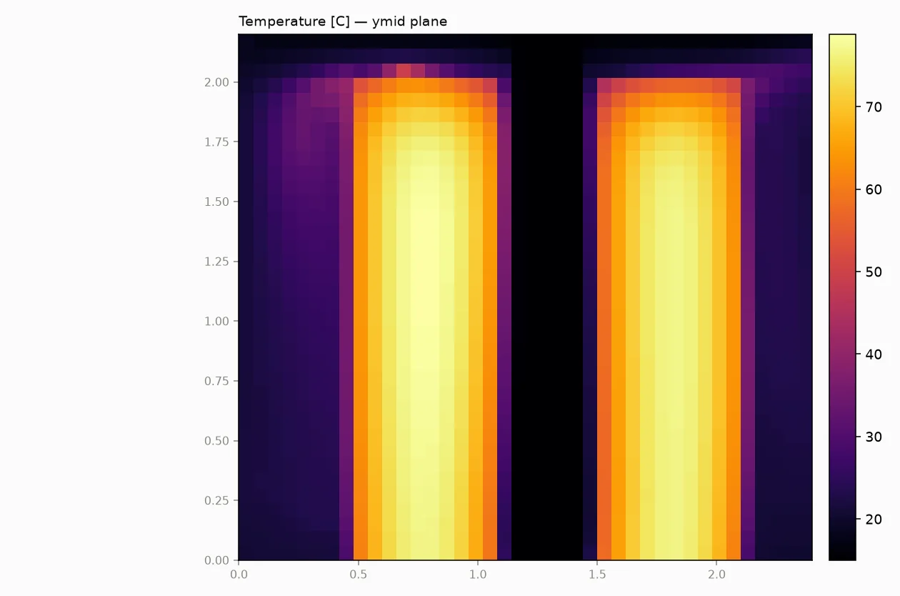
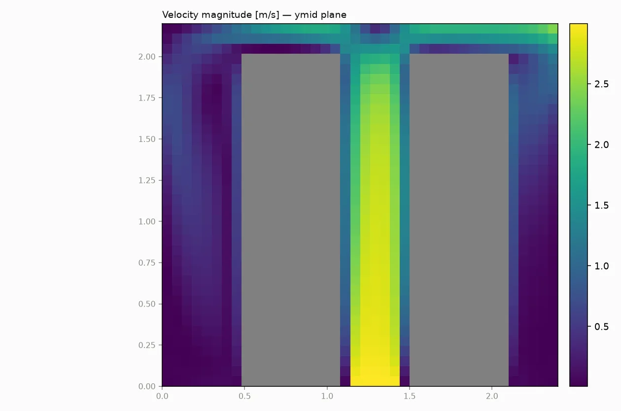
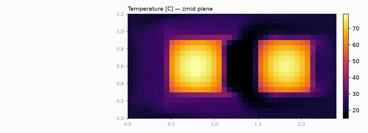
An aisle segment holding two 6 kW server racks, cooled by a CRAC floor supply blowing 15 °C air at 3 m/s up the gap between them, with the return grille at the top far end of the room. The client wanted rack hotspot temperatures against an 85 °C component limit, the energy split between air removal and heat soaking into the racks, and a picture of where the supply air actually travels — does it reach the racks or short-circuit to the return?
What the pipeline ran
Smidr's structured finite-volume CFD solver: incompressible projection on a staggered grid, first-order upwind transport, conjugate heat transfer with per-solid film coefficients, Boussinesq buoyancy, and Smagorinsky eddy viscosity. The grid was 40 x 20 x 36 (28,800 cells), run for 25,000 time steps covering 83.1 seconds of simulated time, in 274 seconds of wall time. Eight automated QA checks ran on the result: seven passed, one warned — and that warning set the verdict.
The verdict
- Both rack temperature checks pass: rack A peaks at 78.8 °C and rack B at 77.0 °C against the 85 °C limit
- Steady-state check warned: still transient after 25,000 steps — the pipeline downgraded itself and labeled all fields a snapshot, not a final answer
- At cutoff, 5.5 kW of the 12 kW input was still flowing into rack thermal mass, so the snapshot hotspots are not settled steady-state values
Key numbers
| Metric | Value | Note |
|---|---|---|
| Verdict | CONDITIONAL | Both rack limits pass, but flow was still transient at cutoff — fields are a snapshot |
| Rack A hotspot | 78.8 °C | vs 85 °C limit — 6.2 °C margin at the 83 s snapshot |
| Rack B hotspot | 77.0 °C | vs 85 °C limit — 8.0 °C margin at the 83 s snapshot |
| Heat input | 12,000 W | Two 6 kW racks |
| Heat rejected at boundaries | 6,498 W | The other 5,506 W was still charging rack thermal mass — proof the run had not reached steady state |
| Energy balance error | 0.03% | Sources vs boundary fluxes plus storage; mass balance closed to 0.00% |
| Peak air speed | 3.0 m/s | CRAC floor supply jet at 15 °C between the racks |
| Grid | 40 x 20 x 36 (28,800 cells) | Smallest solid resolved at 10 cells across (3 recommended minimum) |
| Wall time | 274 s | 25,000 steps, 83.1 s of simulated time |
Quality, stated plainly
Seven of eight automated QA checks passed: the solution stayed finite, post-projection divergence was 2.09e-14 1/s (mass conserved to machine precision), inflow/outflow imbalance was 0.00%, and the energy budget closed to 0.03% once thermal storage in the racks was counted. The eighth check is the honest one: after 25,000 steps the flow was still transient, so the pipeline refused to call this a converged steady state — it downgraded its own verdict to CONDITIONAL and instructs you to treat every field as a snapshot at 83 seconds. With 46% of input power still soaking into rack thermal mass, the reported hotspots will keep climbing toward steady state; the 6-8 °C margins are provisional. The method notes add two more caveats up front: first-order upwind transport is diffusive, so integral quantities (component temperatures, heat splits) are trustworthy while fine flow structure is not, and the film coefficients are model inputs that deserve a sensitivity sweep before hard sign-off.
Figures from the run
Why this matters
Before you commit to a CRAC capacity or a rack layout, this is the five-minute screening run that tells you whether cooling headroom exists and shows you the recirculation pattern that a spreadsheet estimate cannot. Just as important is what the pipeline did when the answer wasn't clean: instead of reporting a comfortable pass, it flagged that the racks were still heating at cutoff and downgraded its own verdict. A tool that tells you when not to trust it is the one you can actually use for go/no-go decisions.
- Not steady state: still transient after 25,000 steps (83.1 s simulated) — all fields are a snapshot, and 5.5 kW of the 12 kW input was still charging rack thermal mass at cutoff
- Screening fidelity: first-order upwind transport is diffusive — trust integral quantities (rack temperatures, heat splits) over fine flow structure
- Film coefficients (30 W/m2-K per rack) are model inputs; a sensitivity sweep is recommended before hard sign-off
- Single grid of 28,800 cells with Smagorinsky eddy viscosity — no mesh-refinement study in this run; the resolution check only confirms 10 cells across the smallest solid
- Single aisle segment with two racks; air modeled as incompressible with Boussinesq buoyancy
Your part. Your question. Same rigor.
Send us the geometry and the question — get the analysis, the honest error bars, and a verdict you can defend.
Request pilot access